Leaderboard
Popular Content
Showing content with the highest reputation on 07/02/2020 in all areas
-
You're welcome anytime.2 points
-
No problem. Happy to help.1 point
-
There are only 2 versions of Autocad. The full version and Autocad LT, but they can both insert images with transparency. To insert your PNG file, use the Xref Manager. Type XREF at the command prompt to open the manager, then right click anywhere inside the "File References" area and choose "Attach Image". This will allow you to insert the PNG file and then you should be able to set the transparency in the Properties palette. When you drag and drop the image it will insert into the drawing as an OLE object and I don't believe you can set background transparency on that type of object. You can't import images through File>Import. That's for importing CAD files.1 point
-
ALWAYS this. Even if the PDF is very clean and simple.1 point
-
What are your computer specs? What program did you use to convert the pdf? What is the dwg file size after you converted the pdf? I agree with BIGAL. The problem is probably the sheer number of individual line segments created by the pdf conversion. A better approach would be to attach the pdf and then trace over it.1 point
-
Table is best done with vla-AddTable. Not saying it's impossible, but it's a lot easier that way.1 point
-
another, delta (defun c:tt (/ p1 p2 en obj ) (and (setq p1 (getpoint "Specify point ")) (setq p2 (getcorner p1 "opposite corner ")) (setq en (entmakex (list '(0 . "LINE") (cons 10 p1) (cons 11 p2)))) (setq obj (vlax-ename->vla-object en)) (princ (strcat "\nArea=" (rtos (apply '* (mapcar '(lambda (a b) (+ a (abs b))) '(0 0) (vlax-get obj 'delta) ) ) 2 3 ) " M\U+00B2" ) ) (entdel en) ) (princ) ) WCS1 point
-
With visual drag box. (defun c:2ptarea ( / co-ord x y ) (command "rectang" (getpoint "pick p1 then drag") pause) (setq co-ord (mapcar 'cdr (vl-remove-if-not '(lambda (x) (= (car x) 10)) (entget (entlast))))) (setq p1 (nth 0 co-ord) p2 (nth 1 co-ord) p3 (nth 2 co-ord) p4 (nth 3 co-ord) ) (setq x (abs(- (car p1)(car p2)))) (setq Y (abs (- (cadr p1)(cadr p4)))) (setq parea (* x y)) (alert (strcat "area is " (rtos parea 2 2) " Length is " (rtos X 2 2) " Height is " (rtos Y 2 2))) (command "erase" "l" "") (princ) )1 point
-
(defun c:aof (/ 1p 2p wd ht) ;; aof = Area on the fly. ;; (and (setq 1p (getpoint "\nSpecify base point : ")) (setq 2p (getcorner "\nOpposite point : " 1p)) (setq wd (distance 1p (list (car 2p) (cadr 1p))) ht (distance 2p (list (car 2p) (cadr 1p))) ) (princ (strcat "\nWidth = " (rtos wd 2 4) " Height = " (rtos ht 2 4) " Area = " (rtos (* wd ht) 2 4) ) ) ) (princ) )1 point
-
Rather than switching to Model Space then back to Paper Space the REGENALL command regenerates the entire drawing and refreshes all viewports. REA is the default command alias.1 point
-
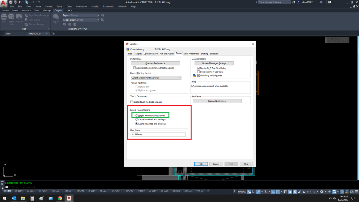
OPTIONS > SYSTEM tab. Select the item in the green box shown in the attached image. My advice is not to do it though. REGEN is a hog and will take more time to change layouts. How much more time depends on what kind of hot rod video processor system you have. I personally am more than happy with REGEN on demand.
 1 point
 -
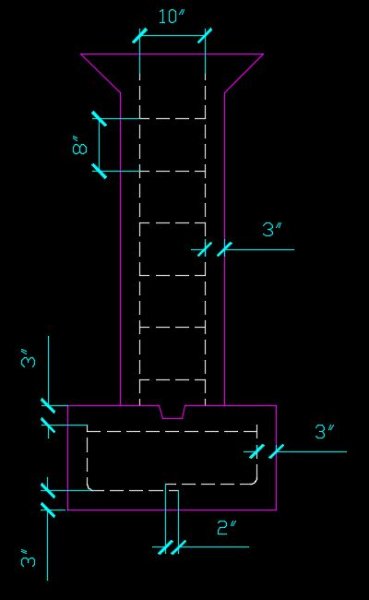
An example of what one former P-F student did.
1 point
-
My point is that when you scale something in model space and try to dimension it in model space you WILL affect the dimensions. One way to overcome this is to create a dimension style that uses a scale factor. This can be changed in your dimension style on the FIT tab where it says "Scale for dimension features" > "Use overall scale factor". In your case I am guessing this would be a scale factor of 4. This new dimension style is used only to dimension the enlarged details. Use your normal dimension style for objects that have not been scaled. Another option would be to use your normal dimension style BUT override the dimension AutoCAD uses by substituting the correct dimension.1 point