Leaderboard

Popular Content
Showing content with the highest reputation on 07/08/2019 in all areas
-
Like this ... (setq dir (angtos (angle p1 p2) 1 4) dis (rtos (distance p1 p2) 2 3) tang (angtos (angle p1 p2) 2 4) ) (setq dir (vl-string-subst "%%d" "d" dir)) ;; display with the degrees symbol not the letter d. (command "text" "j" "bc" p4 theight tang dir) (command "text" "j" "tc" p5 theight tang dis) (command ".rotate" pause pause pause p3 "180") ...1 point
-
Have you looked at some of the other non Autodesk commercial products ? That do a lot more, yes there is a cost.1 point
-
I used the Distance command to measure the diameter going from a quadrant on one side to the quadrant on the opposite side. Students: When it comes time to place text in your drawing you are expected to orient the text parallel to either the centerline of a road or a property line. While this may be easy when text is horizontal or vertical (enabling Orthomode) you may find it somewhat more difficult to do when lines are at an angle. One way to address this situation is to use the SNAPANG command which allows the user to reorient their crosshairs to match the angle of a particular line. Invoke the command. You're prompted for the new angle. Assuming we don't know the angle we can pick one end of the line (I like going left to right) then the other end of the same line and the crosshairs will reorient themselves to match the line's angle. To reset the crosshairs to their "normal" position repeat the SNAPANG command and this time type "0" for the angle. The result should be normal straight up and down/sideways crosshairs . Got it? Good. Now go do it.1 point
-
1. Your trees measure 1.25 when they should measure 15 (we're talking diameter). Not sure how you managed that. 2. It is never a good idea to attach one's drawing to a post as other P-F students could "borrow" your hard work and pass it off as their own. Either remove the attached drawing or delete the post. If you want to share drawings with me go to my visitor's page and leave a message with your email address. I'll contact you after receiving the message. Re: trees. Here is an option I should have thought of yesterday. Invoke the BEDIT (Block Editor) command and select one of the tree blocks. Inside the editor use the Scale command and increase the scale of the tree by a factor of 12 (1.25 x 12 = 15). Exit the block editor and when asked if you want to save your changes respond "Yes". Now all your trees should have a diameter of 15.1 point
-
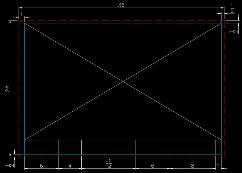
I recently had a student message me regarding the title block and border asking for help drawing it. Of everything the student is asked to draw for this project the title block and border should be the easiest task to accomplish. The full instructions are on page 16 under the heading "Preparing the plat map for plotting." The student is given the overall size of the drawing (24x36), the minimum offset from the cutting edge to the border (1/2") and the offsets for the title block area at the bottom of the sheet. Note that I elected to increase the left hand offset from 1/2" to 1". I've reproduced them here for your benefit. Note: the colors I used are for display purposes only and may not be those called for in the instructions. Keep in mind that when you are finished the title block and border are going to be the size of a postage stamp compared to the subdivision or plat map. It has to be scaled up. A scale factor of 50 will do quite nicely. Once the title block and border has been saved as a block insert the block and specify the scale I just gave you then move the block into position around your plat map. Oleson Village and the surrounding streets should fit quite nicely in the area where you see the yellow "X" in the image above. The red dashed line is considered the cut line. The cyan colored lines are the border. Got it? Good. Now go do it. Warning: do NOT ask me to give my title block and border block. Ain't going to happen. No how...no way.
 1 point
 -
I replied to both of your emails which I did not see until this morning. I explained what was wrong with your latest drawing and gave you explicit information on how logical the streetlines are laid out relative to the boundary of the subdivision. Much of what the student is being asked to draw can be accomplished by first getting the subdivision boundary correctly drawn up (it's four sided) then using the OFFSET command to create both the centerlines of five out of the seven surrounding streets and their streetlines as well. The same command can be used to create the lot lines for five out of the eight lots as well as the sidewalk, grassy strip and curb that fall within the subdivision for SW 85th Avenue and SW Village lane. Note that if a streetline width is 50 feet then the centerline will be equidistance from both or 25'. Or, put another way, locate the street centerline then use the OFFSET command to create the streetline on either side. The distance from one to the other should be the same for both sides. One last thing. As regards the title block and border. Once you have drawn it as per the instructions you need to scale it UP to fit around your subdivision. This is the old school method of doing these types of drawings but it does work. Don't leave the title block and border sitting down in the corner of your drawing at the original size (a postage stamp by comparison to the subdivision) as you will have points deducted from your grade.1 point
-
I thought I pretty much explained how to do it in that very same post you reference. The center of the cul-de-sac is located using coordinates supplied in the project instructions which I believe are X=1421125.75 / Y=783525.60. The cul-de-sac has a radius of 50' and the streetline width is also 50' (again, from the instructions). The west streetline of SW 85th Avenue is 120' east of the subdivision boundary and it is also parallel to it. The east streetline would be parallel to the west streetline. The "short line at the center" is the centerline of the street and is located equidistant between the two streetlines meaning it is 25' from both (straight down the middle of the road). You should have been done with this project back in November. What happened, did you take a vacation or something?1 point
-
The basepoint can be wherever you want it to be but a good CAD tech will usually pick somewhere on the geometry (a corner for example) using his/her OSnaps. P-F fails to mention the exact scale factor instead opting for the vague "scale to fit" description. Start with 40 and increase/decrease in units of 10. Of course the border is supposed to fit around the entire subdivision and adjacent roads. Anything else would look rather odd don't you think?1 point
-
The benchmark symbol is located on the street line intersection of SW Oleson Road and SW Washington Street. This is displayed on any number of images showing Plate 1 of the Oleson Village project posted here at CADTutor in the Student Project Questions forum. Roman simplex and Roman duplex are identified by the font names of Romans and Romand respectively. Re: north arrow. You can draw/use any north arrow you care to choose. It can be simple or elaborate. A simple Internet search using the words "north arrow" should turn up dozens upon dozens of representative symbols. Pick one or design your own unique version. Instructions for creating the title block and border are included in the project description. Do we really have to tell you what page they can be found on? Look on page 16 under the heading "Preparing the Plat Map for Plotting." If reading comprehension is not your strong point then pick up the phone and contact your instructor. That's part of what you are paying you tuition/fees for. Demand your moneysworth.1 point
-
Re: Tree block. As per the instructions on page 4 of the project PDF create the tree block on layer "0" which should have its color set to white. In this example we'll go for simplicity so our tree will be a plain circle. Start the Circle command and when prompted for the center point pick any open spot on your screen and click once. Look at the command line. It now asks you to specify the radius which is the default response from AutoCAD. Type in the number "15" then hit the Enter key. Now start the Point command. When prompted by AutoCAD to "Specify a point" pick the center (use your center Osnap for this) of your circle. You should have a circle with a point at its center showing on your screen. Start the WBlock command. This command allows you to create a block and save it to your hard drive. When the Write Block dialog box appears onscreen click on Base Point > Pick point button. Back in your drawing pick the center of the circle using your Node osnap. This will be the insertion point for your new block. Returning to the dialog box click on Objects > Select objects button. Back in your drawing select the circle and the point. Look at your command line. AutoCAD will tell you "2 found". Hit the Enter key to return to the dialog box. Now you have to save your block. Under the heading Destination > File name and path use the Browse button (button with three dots ...) to navigate to the Desktop and save the block under the name MyTree. Click Save then OK and you are done. How do we get the block into our drawing? We use the Insert command. Do you know how the command works? Yes or No?1 point
-
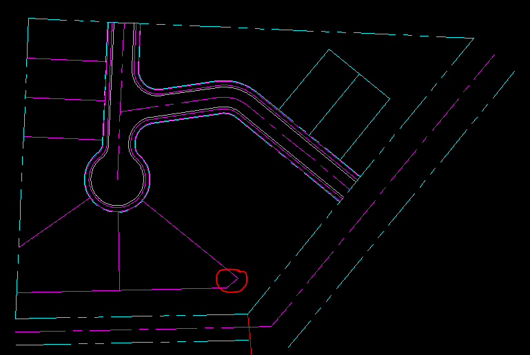
Oleson Village - Lots 6, 7, & 8. One slight correction. I forget the 23.06 property line in a previously posted image for lot #6. I circled it in the above image. The R.O.W. between lot #7 and SW Oleson Road should be 40 feet.
1 point
-
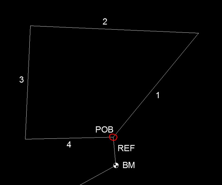
Constructing the boundary. You start at the Point-of-Beginning (POB) as circled in red. This is located 113.66 feet from your benchmark at a bearing of N5d27'23"W. (the letter 'd' is used to tell AutoCAD you mean degrees). You are given the first three boundary lines. Start the line command, pick the endpoint of the POB line and go counter-clockwise entering the distance and bearing as called for in your instructions. This can be done consecutively to avoid restarting the line command each time. The last boundary line you draw in on your own as it merely goes from the end of the third boundary line back to the POB. To check your work (using LIST) this line should have a length of 352.97 and a bearing or angle of N88d46'03"E.
1 point
-
Not sure about I have understand you right, just try the project ~'J'~ UsingVlax.zip1 point