Leaderboard


Popular Content
Showing content with the highest reputation on 05/22/2019 in all areas
-
I would agree that from outward appearances, Autodesk is looking for phase out resellers. Certainly a lot of the smaller "mom and pop" shops have been gobbled up by some of the larger ones, but there is no "rule" that "smaller vendors" can't be an Autodesk reseller. (whatever the definition of "smaller vendor" means....).1 point
-
Yes I do this as I create the Layouts, so usually not really a problem for me. Try the LISP section, someone may have an automated solution.1 point
-
I copied all the viewports on to a different layer and then scaled them to suit. Then placed that Key Plan (with numbers) onto each layout to show its position in the whole. Each layout covered a whole sheet. Every project is different, but my example might give you an idea.
 1 point
 -
It's annoying is all, we had to fight tooth and nail 14 years ago to move over to AutoCAD, albeit LT, as the locally produced "CAD" programme Drawing Express wasn't up to the task of a large medium rise scheme we were about to start, In my opinion we are in the same boat now as we are working on even larger developments but expected to do them in less time. Revit would help massively. The only thing we'd be likely to use out of the AEC package would be Revit and Navisworks. Maybe AutoCAD for site plans as I recall Revit does nice 3d representations of the site but it is a bugger to hatch the surfaces to indicate what they are. Happy to be proved wrong on that!1 point
-
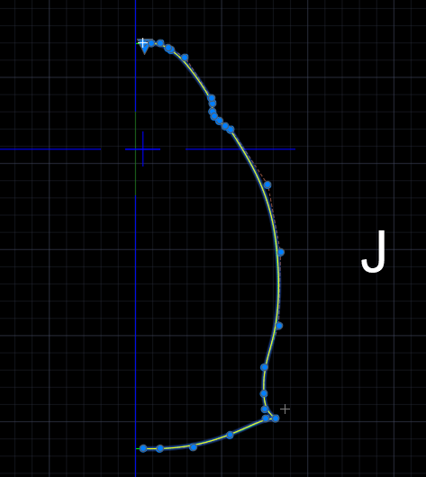
Rather than using polylines for the sections I think you should consider making the half section single splines. Are you comfortable with the manipulation of Fit and CV points of a spline? If not, you might consider "tracing" some of your polyline profiles, or the pdf drawing to create a spline that is a satisfactory representation of the shape. I would start by creating a spline using a dozen or so fit points along the profile. Do not worry about the resulting curve duplication the original. Use close together fit points where there are abrupt changes in curvature. Use few fit point where the curve is relatively smooth. The fewer the fit points the less likely you will get undesired ripples. The next step is to change the editing mode to Control Vertices and see how you can improve the fit by moving the CVs. Use splinedit e a to add additional CVs if they are needed. If you need a sharp corner in the spline then drag two CVs so that they are coincident. I am in the habit of creating profiles in a CCW direction. In 3ds Max this ensures that surface normals are pointing outward and reduces confusion later in the modeling process. The attached file includes your polyline profile (green) for station J and a spline (yellow) I quickly created. It needs some tweaking but you can get a feel for the CV layout. It is important to note that the first two and last two CVs of a spline control both the radius of curvature and the slope of the spline at the ends. If you do not want a crease at the bottom of the fuselage for instance, make sure that the last two CVs are in line horizontally. Your polyline has 546 vertices while the spline has 28 CVs. I think you will find you will get a better quality solid model using splines and not polylines. section-J.dwg
1 point
-
I see a few major problems with your profiles. 1. The starting points for each profile are not consistent. The yellow dot shows where each polyline starts. YOu want them all to start at the same relative position (e.g., bottom corner or center top, or...). 2. The polylines do not go in the same direction. G,H,and J are clockwise whereas K and L are counter clockwise. They should. 3. The polylines have way too many vertices. 478 for L, 544 for K, etc. ! I think creating half profiles and mirror after making a solid is a good strategy.
1 point
-
The process is not for the faint of heart. First, a person has to be comfortable with setting up and using 'beta' release software. This add-in specifically: . That Add-in can be seen in action here: https://knowledge.autodesk.com/support/autocad/learn-explore/caas/screencast/Main/Details/a3afe1be-968d-421c-81f6-167c375abfca.html https://knowledge.autodesk.com/support/autocad/learn-explore/caas/screencast/Main/Details/1d47a745-4bd2-4bef-9e5d-8cd087553ac6.html The latest version (still in testing phase) handles Solids and Surfaces, and I used that to get locations for the Isocurves. The beta in that link only handles solids so you would need to copy the surface, SurfScult it into a solid, evenly divide the resultant UVMap into 7 sections, that project back to the solid. Those positions align with those of the original surface.1 point