Leaderboard


Popular Content
Showing content with the highest reputation on 02/03/2019 in all areas
-
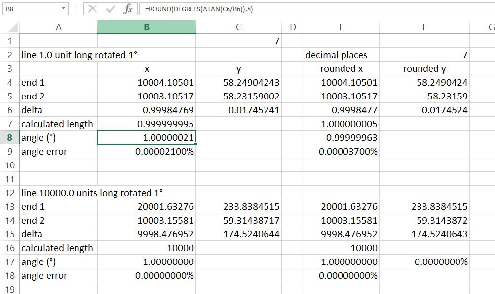
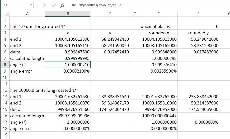
The issue of the difficulty of getting accurate and precise angles in CAD is due to several factors. One of them, as mentioned, is the fact that some base ten numbers cannot be exactly represented in binary. Just as 1/3 requires an infinite number of decimal places to represent it perfectly using the base 10 number systems, 1/10 (base 10) is an irrational fraction in binary (base 2). Another issue is the finite number of significant figures for a coordinate (AutoCAD uses about 15 significant figures). I think a more significant reason for angle errors in CAD is the necessary rounding required to position a line at an angle. Getting an accurate angle for a line is further constrained by the length of the line. Consider the following. Create two perfectly horizontal lines one 1.0 units long and the other 10000 units long. Now rotate each line by 1°. Here’s a sample of the results you get using list to get the coordinates of the lines to 8 decimal places. Note that the shorter line’s rotation is less accurate but just as precise as the long line. Columns E and F round the coordinates to 6 decimal places showing the effect it has on the precision of the rotation. This example helps to show that longer lines can be rotated more accurately than shorter lines. It is good practice to use points as far apart as possible when making angle calculations. Horizontal, vertical, and lines at 45° will be accurately positioned as will lines with a discrete pitch (eg. 3:4).
 1 point
 -
Related discussion on the BricsCAD forum: https://forum.bricsys.com/discussion/22905/autocad-educational-stamp-how-does-bricscad-handle-this1 point
-
See this recent post for more information on why this issue arises.1 point