Leaderboard
Popular Content
Showing content with the highest reputation on 01/23/2019 in all areas
-
Here's a version with 4300 objects deleted (blocks, polylines, hatches, etc), who knows if any of it was required? test.dwg1 point
-
You can try instead. (defun c:replace1 (/ text sel int) (setq text "this is a description text") (if (setq sel (ssget "_:L" '((0 . "MTEXT,TEXT")))) (repeat (setq int (sslength sel)) (setq e (entget (ssname sel (setq int (1- int))))) (entmod (subst (cons 1 text) (assoc 1 e) e)) ) ) (princ) ) DXF Group Code 3 is about Text string that exceed more than 250 chars if I am not mistaken so read THIS for more info.1 point
-
@Tharwat FWIW, I'd use vla-put-textstring. Large mtext strings are broken up into multiple 3 codes so entmodding 1 is unreliable.1 point
-
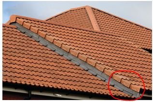
I found this side view of a roof covered with double roman roof tiles. It may be of some help to you.
 1 point
 -
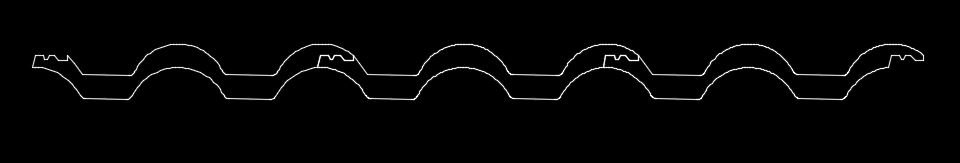
This is what the profile of three double roman roof tiles would look like.
1 point
-
The only way I can reproduce the issue is to toggle the View Direction setting. Is it possible that the style definition has changed? As always, it would help to have more information, especially a drawing that includes the relevant objects.1 point
-
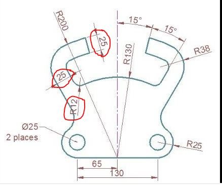
I have to disagree with you. The larger radius should be 37 not 38. The distance between the inner and outer linework remains a constant 25 units as called for in two different locations. But...I too have made an assumption and that is all four inner (smaller) radii are 12 (12+25=37). I could be wrong.
1 point
-
Eldon, That's one of the great things about AutoCAD, as well as other software. There's always more than one way to accomplish a given task. And I'm always amazed at how other people come up with very ingenious ways of doing things. That's what's great about this Forum.1 point
-
Some "symbols" can be found within various fonts. However, if you are looking for free AutoCAD blocks there are numerous places on the Internet where such entities can be found. All it takes is a simple search.1 point
-
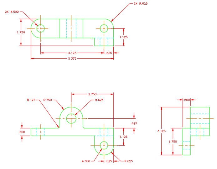
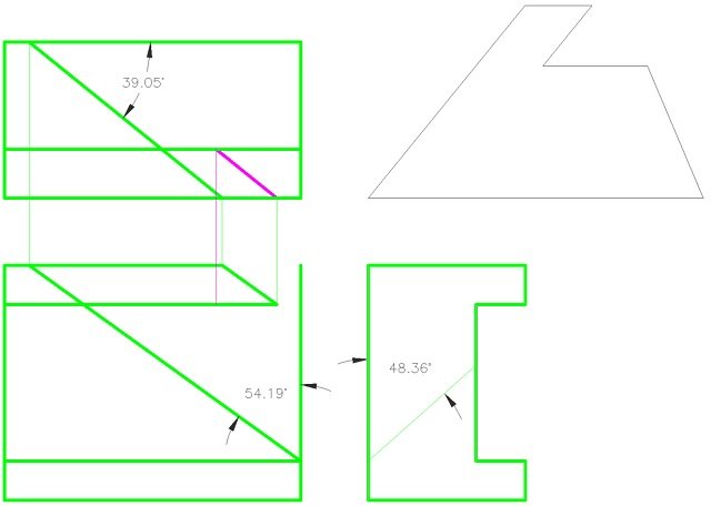
Cleaning out the house as we are moving discovered this student project. It was done when I was about 15 years old, as much as I hate to say it that is 50 years ago. But its still a relevant project today.
1 point
-
Three things immediately come to mind. 1) Top view - I would move the reference to the diameter of the hole on the left side over to the right side and avoid crossing an extension line with a leader. 2) Front view - I would move the R.625 notation to the other side so the leader doesn't cross an extension line. 3) AutoCAD has a dimension break feature that could be used to break extension lines that cross each other.1 point
-
And of course it would be more difficult as you seem to have been doing it upside down. All my old pens, squares, and compasses got lost in a house move 18 years ago. Never replaced them as I had CAD at home by then.1 point
-
I started 50+ years ago as well, at my grandads drawing board (but I'm only 58), I don't have any drawings but I do still have some of the tools (pens etc).1 point
-
Is this a bit better?
1 point
-
The three angled lines in the left diagram are indeed parallel, but there is no starting point measured for the center of those 3. You have assumed that the angle of the diagonal in the right hand diagram is the same as those in the left (mirrored) it isn't! The only given is the lower starting point of that diagonal. If you first construct the front view you can find the correct top starting point for the middle of the 3 left diagonals. And then from there start constructing the auxiliary view of the cut plane.
1 point
-
Whats wrong with 1024 x 760 or 640 x 480 better still a green monochrome screen ! I grew up with a green screen and every one said wow look at that. What you have colour ! $k looking at your 13" screen from 4' away may be worth it. How many of us reach for their glasses to read their phone, go less spend the extra on a 24" 4k external screen.1 point
-
This computer I'm working on has suddenly stopped showing the nodes, no matter what value I assign to PDMODE. I divide lines to equally space window mullions and I have used this process dozens of time. Suddenly, it no longer works. I restarted AutoCAD and when that didn't work I shut everything down and cold booted the box. The nodes are still a no-show. ??? Ooops, my bad. Turns out the current layer was DEFPOINTS and we all know about that layer.1 point