Leaderboard


Popular Content
Showing content with the highest reputation on 10/25/2018 in all areas
-
I wrote a quick Lisp to map an image onto a ... "sphere". Sometime in the (near?) future I will try to improve it, for the moment the image resolution is poor. I used a 3d mesh and AutoCAD limits its dimensions do 256x256. If someone wants to play with the lisp I wrote, draw a 2d shape starting from point 100,0,0 to right. Use a solid hatch on the closed shapes, enter the PLAN command, and maybe do a zoom to "extents". Start the lisp by typing "Miki" and... wait. On my computer it took almost 2 minutes to create the model. Have fun! CADTutor.LsP
 1 point
 -
Thanks - of course, fix on its own would yield the same - _$ (mapcar 'fix '(2.1 2.9 3.14 0.15)) (2 2 3 0) But the inclusion of the 1e-8 'fuzz' accounts for rounding of doubles and avoids situations like this: _$ (fix (- 8.2 0.2)) 7 Though, when used in practice, one should really account for the possibility of negatives since: _$ (fix (+ -2 1e-8)) -1 And so, perhaps a better suggestion would be: (setq lay (itoa (fix ((if (minusp elev) - +) elev 1e-8))))1 point
-
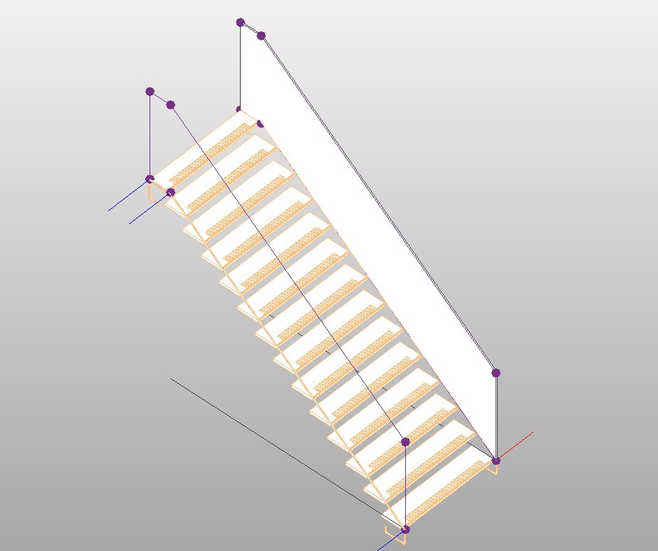
You can do this by loading the stair into the conceptual mass environment. It's better for the kind of job you want to do. For the parapet you can create a family based on adaptive points that can reports the parameters of the perimeter, area and some lengths ... So: 1) new conceptual mass family (you have 3d snap option, reference lines etc) 2) import the stair ---> i suggest to import a cad file where the stringers are fixed, it's enough to draw some lines on the existing geometry to allow the snap when you import the file. 3) built a separate family for the parapet based on 3 adaptive points with parameters where you can set, height, materials etc, and some reporting parameters for area and dimensions. 4) otherwise you can draw directly in the family where you imported the dwg of the stair, like in the image below.
1 point
-
Because the structure of my code won't allow you to Why have you removed the headers from all of my functions, violating my terms?1 point
-
Going through Engineering Drawing with Worked Examples 1 by M.A.Parker and F.Pickup (first published 1960) and creating models as per the drawings. Got to final problem Flange Coupling (p.219-220). I've created the parts as per the drawings (Flange 2 off, Driving Pin 4 off, Bush 4 off, Washer 8 off) but now need to assemble. I'm not a mechanical engineer so I don't know how to proceed even though the text gives some indication as to the assembling "....The driving pins are attached to each flange alternatively by a nut (they give a note in the drawings "also required 8 off Hex Nuts M10-6H") and washer. The bushes are centrally placed in the 28mm diamater bores and retained on the driving pins by a nut and washer. Note that the parts are assembled so that there is a gap between the flanges and shaft ends".... Do I need to create a shaft? I know I need to create a suitable key but will have to gen up on Inventor's Generators first. Anyone in a position to construct an assembly drawing (not an .iam as I want to assemble myself). Thanks in advance. PS. Have those familiar with the book mentioned above ever seen Engineering Drawing with Worked Examples 2. Seems extremely difficult to get hold off!!! Bush.ipt Driving Pin.ipt Flange.ipt Washer.ipt1 point